

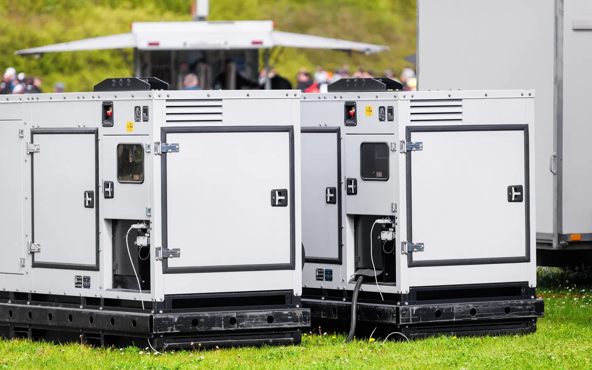
Distributed Gensets Run Out of Sight
A genset at a remote tower, a hospital, or a far site only tells its story through a paper logbook that someone fills in days later, if at all. You find out fuel was low after the unit failed to start, you cannot prove run hours for a service contract, and a fault sits unnoticed until the next visit. Manual logs are slow, error-prone, and useless for a fleet spread across sites. Live data pulled straight from the engine controller replaces them, so run hours, fuel, load, and faults reach you in real time.
A component of the broader Telematics and GPS Tracking capability, often deployed with Remote Equipment and Machine Monitoring.
WHAT'S INCLUDED
Hardware and Software for Genset Telemetry
Controller Integration
Live data is read from DeepSea and ComAp style panels and PLC-based control panels over Modbus RTU and TCP, and from the engine over CAN using SAE J1939. Where a panel has no data port, added sensors keep the unit covered.
Run Hours and Load
Run and stop state, run hours, load and power output, and voltage and frequency on both mains and genset are captured. Run hours feed service scheduling and contract billing so a maintenance visit is triggered by real usage rather than a calendar guess.
Fuel Monitoring
Fuel level is read from the controller or from an added capacitive or ultrasonic sensor, consumption is tracked per run, and sudden drops that suggest theft or a leak are flagged. Low-fuel alerts fire before the unit fails to start.
Fault Codes and Diagnostics
Controller fault and shutdown codes are mapped to plain-language alerts, including high temperature, low oil pressure, overload, failure to start, and unexpected shutdown. Coolant temperature, oil pressure, and battery voltage are logged for trend analysis.
Remote Start Context
Why each genset ran is logged, whether a mains-failure auto-start, a scheduled test, or a manual start, where the controller exposes it. That keeps a 20-minute test run from being mistaken for a real outage in your records.
Alerts and Fleet Dashboard
Alerts go out by SMS, email, and app notification, and every genset across every site rolls into one dashboard with per-unit drill-down, fuel and run-hour reports, and exports for billing, compliance, and maintenance planning.
DATA ACQUISITION
Reading the Genset Three Ways
Every site has a different controller and a different wiring reality. Whichever data path the unit supports is used, so you get full telemetry without changing the panel.
Modbus from the Panel
When the controller exposes a Modbus register map over RS-485 or Ethernet, it is read directly. This gives the richest data set, including load, fuel, run hours, and fault registers, with no extra sensors.
J1939 from the Engine
For electronic engines the CAN bus is read using SAE J1939, picking up engine speed, coolant temperature, oil pressure, and fault PGNs straight from the ECU when the panel does not surface them.
Added Sensors
On older mechanical sets with no data port, a run-signal pickup, current transformers for load, and a fuel sensor are wired in. The field unit turns these into the same telemetry stream as a digital panel.
ARCHITECTURE
From Controller to Cloud Dashboard
Field Unit
A rugged gateway built on an STM32 with isolated RS-485 and CAN interfaces and a cellular modem sits at each genset. It buffers data locally so nothing is lost when the link drops, and forwards it when connectivity returns.
Ingestion Pipeline
Units publish over MQTT to a broker. The backend decodes Modbus and J1939 payloads, runs the alert rules, and stores readings in a time-series database tuned for run-hour and fuel trend queries across thousands of units.
Dashboard and APIs
The web dashboard shows live status, fault history, and fuel and run-hour reports per site and per unit. REST APIs and webhooks push events into your maintenance, ERP, or billing systems.
STANDARDS AND CONNECTIVITY
Built for Remote, Unattended Sites
Protocol Support
Modbus RTU and TCP and SAE J1939 over CAN cover the controllers and engines in the field. The field unit is electrically isolated to protect against the noisy power environment around a running genset.
Low-Bandwidth Connectivity
Cellular is the default, with NB-IoT or Cat-M1 for fixed remote sites with weak coverage, where low data rate and deep-indoor reach matter more than speed. Ethernet uplink is available where a site network exists.
Field-Ready Hardware
The gateway enclosure is sealed and rated for the heat, dust, and vibration of a genset room or outdoor canopy, with wide-input power and surge protection so it survives the same conditions as the engine it watches.
FAQ
Common Questions
Which genset controllers do you integrate with?
Data is read from the common engine controllers, including DeepSea and ComAp style panels, over Modbus RTU and TCP and over the engine CAN bus using SAE J1939. PLC-based control panels are supported too. Where a panel has no data port, added sensors cover fuel, run signal, and current.
What parameters can you capture remotely?
Run hours, running and stopped state, load and power output, fuel level and consumption, battery voltage, coolant temperature, oil pressure, mains and genset voltage and frequency, and any fault or shutdown codes the controller reports. These are logged on a schedule and on every state change.
Can the system detect and alert on faults in real time?
Yes. Controller fault and shutdown codes are mapped to plain-language alerts and pushed by SMS, email, and app notification the moment they occur. Low fuel, high temperature, overload, failure to start, and unexpected shutdown each raise a distinct alert routed to the right team.
How does it report remote start and stop context?
Start and stop cause is logged where the controller exposes it, such as a mains failure auto-start, a scheduled test run, or a manual start. The dashboard shows why each genset ran and for how long, so a 20-minute test is not confused with a real outage event.
Will it work at sites with poor connectivity?
The field unit buffers data locally and forwards it when the link returns, so no run-hour or fuel data is lost during an outage. Cellular is the default, including NB-IoT or Cat-M1 for fixed remote sites, and an Ethernet uplink can be added where a site network exists.
Can a whole fleet of gensets across many sites be monitored?
Yes. The dashboard rolls up every genset across all sites into one view, with per-site and per-unit drill-down. You see which units are running, total fuel burn, run hours due for service, and any active faults, plus exportable reports for billing, compliance, and maintenance planning.
Ready to Retire the Genset Logbook?
Share your controller types, fleet size, and the sites you need covered to get the data path for each unit and how the fleet dashboard and alerts come together.
Schedule a Free Consultation